今回は画像表示に付いてです。
BITMAP関係
/TFT_eSPI/examples/Generic/drawXBitmap/drawXBitmap.ino
このデモを実行するとLCDにLOGOマーク(下記2種類)が任意の位置に表示されます。

これは関数 drawXBitmap(int16_t x, int16_t y, const uint8_t *bitmap, int16_t w, int16_t h, uint16_t color) によって表示され、関数の各引数は以下の通り
| 引数 | 説明 |
|---|---|
| int16_t x | 表示位置X座標(画像左上隅基準) |
| int16_t y | 表示位置Y座標(画像左上隅基準) |
| const uint8_t *bitmap | BitMapデータ開始のポインタ |
| int16_t w | 画像の幅 |
| int16_t h | 画像の高さ |
| uint16_t color | 色指定 |
デモプログラムではBitMapデータは xbm.h に配列 logo[]として定義されています。このデータを2進数(0,1)で書き直すと以下の様になります。
logo.h
00000000000000000000000000000000000000000000000000000000
00000000000000000000000000000000000000000000000000000000
00000000000000000000000000000000000000000000000000000000
00000000000000000000000000000000000000000000000000000000
00000000000000000000000000000000000000000000000000000000
00000000000000000000000011111100000000000000000000000000
00000000000000000000000011111111100000000000000000000000
00000000000000001110000000111111111000000000000000000000
00000000010000011111111000001111111110000000000000000000
00000000011000111111111111000011111111000000000000000000
00000000111001111111111111110001111111100000000000000000
00000001110001111111111111111000011111110000000000000000
00000001100001111111111111111110001111111000000000000000
00000011000000001111111111111111000111111100000000000000
00000111000000000000011111111111100011111100000000000000
00000110000011111000000111111111110001111110000000000000
00000110001111111111100001111111111000111110000000000000
00001100011111111111111000011111111100011111000000000000
00001100111111111111111110001111111110011111000000000000
00001101111111111111111111000111111111001111000000000000
00001101111111111111111111100011111111000111100000000000
00011101111111111111111111110001111111100111100000000000
00011001111110000011111111111100111111110011100000000000
00011101111111000000011111111100011111110011100000000000
00011001111111111100001111111110011111111001100000000000
00011001111111111111000011111111001111111001100000000000
00011100111111111111110011111111001111111000000000000000
00001100011111111111111001111111100111111100000000000000
00001100001111111111111100111111100111111100000000000000
00001100000111111111111100011111110011111100000000000000
00001100000000001111111110011111110011111100000000000000
00001110000000000011111110011111110011111110000000000000
00000110000000000001111111001111110011111110000000000000
00000111000111110001111111001111111011111100000000000000
00000011000111111000111111001111110001111100000000000000
00000011101111111000111111001111111011111000000000000000
00000001101111111000111111001111111001110000000000000000
00000000111111111000111111001111111000000000000000000000
00000000111111110001111111001111111000000000000000000000
00000000011111100001111111001111110000011100000000000000
00000000001111000001111111001111110000111000000000000000
00000000000011100001111110011111110001110000000000000000
00000000000001111000011110000010000111100000000000000000
00000000000000111111000000000000111110000000000000000000
00000000000000001111111110111111111000000000000000000000
00000000000000000001111111111111100000000000000000000000
00000000000000000000000101101000000000000000000000000000
00000000000000000000000000000000000000000000000000000000
00000000000000000000000000000000000000000000000000000000
00000000000000000000000000000000000000000000000000000000
データの0,1がLCDのドットに対応しています。 この関数は、”1”の部分の色をuint16_t colorで指定します。
デモプログラムは内容は以下の通り。
- 先ずtft.drawXBitmap(x, y, logo, logoWidth, logoHeight, TFT_WHITE);を実行します。
- これでデータの”1”の部分の色をTFT_WHITEに指定しています。
- 予めバックを黒で描いているので実行結果は上記画像左(黒と白のLOGO)となります。
- 次に時間を置いて tft.drawXBitmap(x, y, logo, logoWidth, logoHeight, TFT_BLACK); を実行しています。
- 今度はデータの”1”の部分の色をTFT_BLACK(黒)に指定しています。
- バックと同じ色なので結果としてLOGOが消えます。
- 次に.drawXBitmap(x, y, logo, logoWidth, logoHeight, TFT_RED, TFT_WHITE);が実行されます。
- これは新たに引数、TFT_WHITEが追加された関数で、こちらはデータの”0”の部分の色を指定します。
- これでデータの”1”の部分はTFT_RED。”0”の部分はTFT_WHITEが指定された事になり上記画像右(赤いLOGO)が表示されます。
- 次に.drawXBitmap(x, y, logo, logoWidth, logoHeight, TFT_BLACK, TFT_BLACK); を実行するのでLOGOは消えます。
/TFT_eSPI/examples/Generic/TFT_Flash_Bitmap/TFT_Flash_Bitmap.ino
このデモを実行するとLCD上に下記の3つの画像が任意に表示されます。

キーとなっている関数は pushImage(int32_t x, int32_t y, int32_t w, int32_t h, uint16_t *data) です。引数は以下の通り。
| 引数 | 説明 |
|---|---|
| int32_t x | 表示位置X座標(画像左上隅基準) |
| int32_t y | 表示位置Y座標(画像左上隅基準) |
| int32_t w | 画像の幅 |
| int32_t h | 画像の高さ |
| uint16_t *data | 画像データ開始のポインタ |
drawXBitmap() との違いは drawXBitmap()の画像データは1ビットがLCDの1ドットに対応し、データの”1”の部分に色を指定していました(色指定が1色しか出来ない)が、pushImage() は16ビットでLCD1ドットに対応し、TFT_eSPIのフルカラーでドットの色を指定出来ます。プログラムの画像データは、”Alert.h” ”Close.h” ”Info.h”。各配列共にconst unsigned short型の配列で32x32で定義されています。画像の大きさは32ドットX32ドット。配列の要素1つがLCDの1ドットに対応しています。
この関数にも引数が1個多いバージョンが有ります。pushImage(int32_t x, int32_t y, int32_t w, int32_t h, uint16_t *data, uint16_t transp)。最後の引数は画像データの中で透明色として扱う色を指定します。例えば上記赤丸にバッテンの有る画像ですが、tft.pushImage(180, 100, closeWidth, closeHeight, closeX);で上記と同じ画像。 透明色をtft.pushImage(180, 100, closeWidth, closeHeight, closeX, TFT_WHITE);の様にTFT_WHITEと指定すると、中心のバッテンの部分が白から黒(バックを黒で書いているので白が透明なら黒)になります。下記は実行結果です。

/TFT_eSPI/examples/Generic/TFT_SPIFFS_BMP/TFT_SPIFFS_BMP.ino
このデモプログラムを実行するとLCDに以下の様にオウムが表示されます。
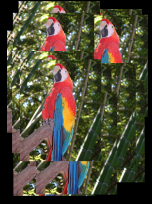
今までと違いFLASHにSPIFFSで保存されたBITMAPファイルを表示します。表示している関数は void drawBmp(const char *filename, int16_t x, int16_t y)。各々の引数は以下の通り。
| 引数 | 説明 |
|---|---|
| const char *filename | 画像データ開始のポインタ |
| int16_t x | 表示位置X座標(画像左上隅基準) |
| int16_t y | 表示位置Y座標(画像左上隅基準) |
ファイルシステムを変更すればSDカードに保存したファイルを表示する事も出来ます。SDカードを有効にする為にTFT_SPIFFS_BMP.inoとBMP_functions.inoファイルを以下の様に修正します
TFT_SPIFFS_BMP.ino
//====================================================================================
//                                  Libraries
//====================================================================================
// Call up the SPIFFS FLASH filing system this is part of the ESP Core
#define FS_NO_GLOBALS
#include <FS.h>

#ifdef ESP32
  #include "SPIFFS.h"  // For ESP32 only
#endif

// Call up the TFT library
#include <TFT_eSPI.h> // Hardware-specific library for ESP8266

// Invoke TFT library
TFT_eSPI tft = TFT_eSPI();

#include <SD.h>
SPIClass sd_spi(HSPI);

//====================================================================================
//                                    Setup
//====================================================================================
void setup()
{
  Serial.begin(115200);

  sd_spi.begin(26, 25, 33, 4);
//  if (!SPIFFS.begin()) {
  if(!SD.begin(4, sd_spi)){
    Serial.println("SPIFFS initialisation failed!");
    while (1) yield(); // Stay here twiddling thumbs waiting
  }
  Serial.println("\r\nSPIFFS initialised.");

  // Now initialise the TFT
  tft.begin();
  tft.setRotation(0);  // 0 & 2 Portrait. 1 & 3 landscape
  tft.fillScreen(TFT_BLACK);
}
- TFT_SPIFFS_BMP.ino
- 18,19行を追加。
- 28から30行。ここでファイルシステムをSPIFFSからSDカードに変更しています。
// Bodmer's BMP image rendering function

void drawBmp(const char *filename, int16_t x, int16_t y) {

  if ((x >= tft.width()) || (y >= tft.height())) return;

  fs::File bmpFS;

  // Open requested file on SD card
//  bmpFS = SPIFFS.open(filename, "r");
  bmpFS = SD.open(filename, "r");

  if (!bmpFS)
  {
    Serial.print("File not found");
    return;
  }
- BMP_functions.ino
- 10行: SPIFFSをコメントアウト。
- 11行: SDファイルシステムを使ってファイルをオープンします。
これで ”parrot.bmp”をSDカードに保存して実行すればデモと同じにLCDにオウムが表示されます。SDカードからの読み込みの為、SPIFFSより若干表示が遅い様に思えました。
JPEG関係
/TFT_eSPI/examples/Generic/ESP32_SDcard_jpeg/ESP32_SDcard_jpeg.ino
SDカードに保存されたJPEGファイルを表示するデモです。SDカードを有効にする為下記の設定を行います。
ESP32_SDcard_jpeg.ino
// The example images used to test this sketch can be found in the library
// JPEGDecoder/extras folder
//----------------------------------------------------------------------------------------------------

#include <SPI.h>

#include <FS.h>
#include <SD.h>

#include <TFT_eSPI.h>
TFT_eSPI tft = TFT_eSPI();

// JPEG decoder library
#include <JPEGDecoder.h>
SPIClass sd_spi(HSPI);

//####################################################################################################
// Setup
//####################################################################################################
void setup() {
  Serial.begin(115200);

  // Set all chip selects high to avoid bus contention during initialisation of each peripheral
//  digitalWrite(22, HIGH); // Touch controller chip select (if used)
//  digitalWrite(15, HIGH); // TFT screen chip select
//  digitalWrite( 5, HIGH); // SD card chips select, must use GPIO 5 (ESP32 SS)
  digitalWrite(17, HIGH); // Touch controller chip select (if used)
  digitalWrite(22, HIGH); // TFT screen chip select
  digitalWrite( 4, HIGH); // SD card chips select, must use GPIO 5 (ESP32 SS)

  tft.begin();

  sd_spi.begin(26, 25, 33, 4);
//  if (!SD.begin(5, tft.getSPIinstance())) {
  if(!SD.begin(4, sd_spi)){
      Serial.println("Card Mount Failed");
    return;
  }
  uint8_t cardType = SD.cardType();

  if (cardType == CARD_NONE) {
    Serial.println("No SD card attached");
    return;
  }
- 25行: HSPIを追加
- 34から39行: ピンアサインの設定
- 43から45行: SDカードをHSPIにし、SDカードを初期化
上記の修正を行った後、JPEGのサンプルファイルをhttps://github.com/Bodmer/JPEGDecoderからダウンロードしSDカードに保存しプログラムを実行して下さい。画像が表示されます。
このプログラムでキーとなっている関数は、void drawSdJpeg(const char *filename, int xpos, int ypos)です。
| 引数 | 説明 |
|---|---|
| const char *filename | 画像データファイル名のポインタ |
| int xpos | 表示位置X座標(画像左上隅基準) |
| int ypos | 表示位置Y座標(画像左上隅基準) |
ここでデータを読み込み、デコードを行っています。デコード後BITMAPの時と同じ tft.pushImage()関数を使ってLCDに表示しています。
LCDに表示する関数がtft.pushImage()なので、void drawSdJpeg(const char *filename, int xpos, int ypos)にもう一つ引数を追加してBITMAPの時と同じ様に透明色を扱える様にして見ました。
drawSdJpeg()
void drawSdJpeg(const char *filename, int xpos, int ypos, int tr_color) {

  // Open the named file (the Jpeg decoder library will close it)
  File jpegFile = SD.open( filename, FILE_READ);  // or, file handle reference for SD library
  bool decoded = JpegDec.decodeSdFile(jpegFile);  // Pass the SD file handle to the decoder,
  uint16_t *pImg;
  uint16_t mcu_w = JpegDec.MCUWidth;
  uint16_t mcu_h = JpegDec.MCUHeight;
  uint32_t max_x = JpegDec.width;
  uint32_t max_y = JpegDec.height;
  // Jpeg images are draw as a set of image block (tiles) called Minimum Coding Units (MCUs)
  // Typically these MCUs are 16x16 pixel blocks
  // Determine the width and height of the right and bottom edge image blocks
  uint32_t min_w = jpg_min(mcu_w, max_x % mcu_w);
  uint32_t min_h = jpg_min(mcu_h, max_y % mcu_h);

  // save the current image block size
  uint32_t win_w = mcu_w;
  uint32_t win_h = mcu_h;

  bool swapBytes = tft.getSwapBytes();
  tft.setSwapBytes(true);


  // save the coordinate of the right and bottom edges to assist image cropping
  // to the screen size
  max_x += xpos;
  max_y += ypos;

  // Fetch data from the file, decode and display
  while (JpegDec.read()) {    // While there is more data in the file
    pImg = JpegDec.pImage ;   // Decode a MCU (Minimum Coding Unit, typically a 8x8 or 16x16 pixel block)

    // Calculate coordinates of top left corner of current MCU
    int mcu_x = JpegDec.MCUx * mcu_w + xpos;
    int mcu_y = JpegDec.MCUy * mcu_h + ypos;

    // check if the image block size needs to be changed for the right edge
    if (mcu_x + mcu_w <= max_x) win_w = mcu_w;
    else win_w = min_w;

    // check if the image block size needs to be changed for the bottom edge
    if (mcu_y + mcu_h <= max_y) win_h = mcu_h;
    else win_h = min_h;

    // copy pixels into a contiguous block
    if (win_w != mcu_w)
    {
      uint16_t *cImg;
      int p = 0;
      cImg = pImg + win_w;
      for (int h = 1; h < win_h; h++)
      {
        p += mcu_w;
        for (int w = 0; w < win_w; w++)
        {
          *cImg = *(pImg + w + p);
          cImg++;
        }
      }
    }

    // calculate how many pixels must be drawn
    uint32_t mcu_pixels = win_w * win_h;

    // draw image MCU block only if it will fit on the screen
    if (( mcu_x + win_w ) <= tft.width() && ( mcu_y + win_h ) <= tft.height())
      tft.pushImage(mcu_x, mcu_y, win_w, win_h, pImg, tr_color);
    else if ( (mcu_y + win_h) >= tft.height())
      JpegDec.abort(); // Image has run off bottom of screen so abort decoding
  }

  tft.setSwapBytes(swapBytes);
  jpegFile.close();

}
追加した引数を68行の関数 tft.pushImage()の第5引数とすれば透明色が使える様になります。

元図(左側)の白の部分を透明に設定したものが右の図です。微妙に色残りしています。白は0XFFFFで指定しているので若干色が違う部分(多分0xFFFEでも白く見える)が透明にならない為か分かりませんがちょっとがっかりです。
PNG関係
/TFT_eSPI/examples/PNG Images/Flash_PNG/Flash_PNG.ino
配列に保存されたPNG画像データを表示するデモです。画像データはpanda.h で定義されそれを表示するのですが、動作がちょっと分かりません。
int16_t rc = png.openFLASH((uint8_t *)buf, sizeof(buf), pngDraw); から始まり、tft.startWrite(); rc = png.decode(NULL, 0); tft.endWrite(); の3つの関数で画像を表示しています。png.openFLASH()で指定したCallBack関数 void pngDraw(PNGDRAW *pDraw) が画像を表示しているようなのですが、この関数画像の1行分しか表示していない様に見えます。でも何故か画像全てが表示されます。
void pngDraw()
//=========================================v==========================================
//                                      pngDraw
//====================================================================================
// This next function will be called during decoding of the png file to
// render each image line to the TFT.  If you use a different TFT library
// you will need to adapt this function to suit.
// Callback function to draw pixels to the display
void pngDraw(PNGDRAW *pDraw) {
  uint16_t lineBuffer[MAX_IMAGE_WIDTH];
  png.getLineAsRGB565(pDraw, lineBuffer, PNG_RGB565_BIG_ENDIAN, 0xffffffff);
  tft.pushImage(xpos, ypos + pDraw->y, pDraw->iWidth, 1, lineBuffer);
}
- 9行:uint16_t lineBuffer[MAX_IMAGE_WIDTH];
- 画像の幅1行分のバッファーを確保
- 10行:png.getLineAsRGB565(pDraw, lineBuffer, PNG_RGB565_BIG_ENDIAN, 0xffffffff);
- この関数の機能が分かりません。
- 11行:tft.pushImage(xpos, ypos + pDraw->y, pDraw->iWidth, 1, lineBuffer);
- 座標xpos,yposに幅pDraw->iWidth、高さ1の範囲にlineBufferの内容を表示。
png.getLineAsRGB565(pDraw, lineBuffer, PNG_RGB565_BIG_ENDIAN, 0xffffffff);の動作が分からないので何とも言えませんが、11行は明らかに、幅pDraw->iWidth、高さ1の画像データの表示(1行のみの表示)です。何でこれで画像が表示されるのでしょうか。
”panda.h”は、PNGファイルそのものでした。 ”parrot.jpg”を画像エディターでPNG形式に変換してSDカードに”parrot.png”と保存。SDカードをLCDにセットして下記のプログラムを実行すると、”parrot.png”の内容が16進テキストファイル”temp.txt”とSDカードに保存されます。
change.ino
#include "SPI.h"
#include <FS.h>
#include <SD.h>
SPIClass sd_spi(HSPI);

void setup() {
  int a;
  uint8_t buf[10];

    Serial.begin(115200);

    sd_spi.begin(26, 25, 33, 4);
    if(!SD.begin(4, sd_spi)){
      Serial.println("Card Mount Failed");
      return;
    }

    File fp = SD.open("/parrot.png",FILE_READ);
    File fp1 = SD.open("/temp.txt",FILE_WRITE);
    a = 0;
    sprintf((char*)buf,"0x%02x",fp.read());
    fp1.write(buf,4);
    while (fp.available()){
      sprintf((char*)buf,",0x%02x",fp.read());
      fp1.write(buf,5);
      a ++;
      if(a == 50){
        fp1.write('\n');
        a = 0;
      }
    }
    fp.close();
    fp1.close();
    Serial.println("OK");

}

void loop() {
  // put your main code here, to run repeatedly:

}
”temp.txt”の内容を”panda.h” の配列panda[]の要素と入れ替えて ”Flash_PNG.ino” を実行すれば、パンダの変わりにオウムが表示されます。
/TFT_eSPI/examples/PNG Images/LittleFS_PNG/LittleFS_PNG.ino
LittleFSでFLASHに保存されたPNG形式の絵を表示するデモです。表示に必要は部分のみ取り出すと以下の様になります。
LittleFS_PNG.ino
#include <LittleFS.h>
#define FileSys LittleFS

// Include the PNG decoder library
#include <PNGdec.h>

PNG png;
#define MAX_IMAGE_WIDTH 240 // Adjust for your images

int16_t xpos = 0;
int16_t ypos = 0;

#include "SPI.h"
#include <TFT_eSPI.h>              // Hardware-specific library
TFT_eSPI tft = TFT_eSPI();         // Invoke custom library

//====================================================================================
//                                    Setup
//====================================================================================
void setup()
{
  Serial.begin(115200);

  // Initialise FS
  if (!FileSys.begin()) {
    Serial.println("LittleFS initialisation failed!");
    while (1) yield(); // Stay here twiddling thumbs waiting
  }

  // Initialise the TFT
  tft.begin();
  tft.fillScreen(TFT_BLACK);

  int16_t rc = png.open("/panda.png", pngOpen, pngClose, pngRead, pngSeek, pngDraw);
  tft.startWrite();
  rc = png.decode(NULL, 0);
  png.close();
  tft.endWrite();
}

//====================================================================================
//                                    Loop
//====================================================================================
void loop()
{
  delay(100) ;
}

//=========================================v==========================================
//                                      pngDraw
//====================================================================================
void pngDraw(PNGDRAW *pDraw) {
  uint16_t lineBuffer[MAX_IMAGE_WIDTH];
  png.getLineAsRGB565(pDraw, lineBuffer, PNG_RGB565_BIG_ENDIAN, 0xffffffff);
  tft.pushImage(xpos, ypos + pDraw->y, pDraw->iWidth, 1, lineBuffer);
}

File pngfile;

void * pngOpen(const char *filename, int32_t *size) {
  pngfile = FileSys.open(filename, "r");
  *size = pngfile.size();
  return &pngfile;
}

void pngClose(void *handle) {
  File pngfile = *((File*)handle);
  if (pngfile) pngfile.close();
}

int32_t pngRead(PNGFILE *page, uint8_t *buffer, int32_t length) {
  if (!pngfile) return 0;
  page = page; // Avoid warning
  return pngfile.read(buffer, length);
}

int32_t pngSeek(PNGFILE *page, int32_t position) {
  if (!pngfile) return 0;
  page = page; // Avoid warning
  return pngfile.seek(position);
}
- 25行でLittleFSを初期化し
- 34行でFLASHに保存されたファイルを読み込む初期化をしています。
- 35,36,37,38行と実行するとLCDにパンダが表示されます。
- 52行以下が実際の描画部分ですが、ちょっと詳細が分かりません。
- 全てCallBack関数の様です。
- pngDraw(PNGDRAW *pDraw)
- ここで表示する位置をxpos,yposで指定
- 前回と同じ1段づつDecodeしてLCDに表示
- その他 pngOpen() pngClose() pngRead()
pngSeek() は名前で何をする関数か想像は付きますが実際どの様に動くのは全く分かりません。
このデモは25行で if (!FileSys.begin()) { としているように、他のファイルシステムでも動きます。以下の様に変更するとSDカードから読み込む事が出来ます。SDカードに”panda.png”を保存して下記を実行すればパンダが表示されます。
SD_PNG.ino
#define FileSys SD
// Include the PNG decoder library
#include <PNGdec.h>

PNG png;
#define MAX_IMAGE_WIDTH 240 // Adjust for your images

int16_t xpos = 0;
int16_t ypos = 0;

#include "SPI.h"
#include <TFT_eSPI.h>              // Hardware-specific library
TFT_eSPI tft = TFT_eSPI();         // Invoke custom library

#include <FS.h>
#include <SD.h>
SPIClass sd_spi(HSPI);

//====================================================================================
//                                    Setup
//====================================================================================
void setup()
{
  Serial.begin(115200);

  // Initialise SD
  sd_spi.begin(26, 25, 33, 4);
  if(!FileSys.begin(4, sd_spi)){
    Serial.println("LittleFS initialisation failed!");
    while (1) yield(); // Stay here twiddling thumbs waiting
  }

  // Initialise the TFT
  tft.begin();
  tft.fillScreen(TFT_BLACK);

  int16_t rc = png.open("/panda.png", pngOpen, pngClose, pngRead, pngSeek, pngDraw);
  tft.startWrite();
  rc = png.decode(NULL, 0);
  png.close();
  tft.endWrite();
}

//====================================================================================
//                                    Loop
//====================================================================================
void loop()
{
  delay(100) ;
}

//=========================================v==========================================
//                                      pngDraw
//====================================================================================
void pngDraw(PNGDRAW *pDraw) {
  uint16_t lineBuffer[MAX_IMAGE_WIDTH];
  png.getLineAsRGB565(pDraw, lineBuffer, PNG_RGB565_BIG_ENDIAN, 0xffffffff);
  tft.pushImage(xpos, ypos + pDraw->y, pDraw->iWidth, 1, lineBuffer);
}

File pngfile;

void * pngOpen(const char *filename, int32_t *size) {
  pngfile = FileSys.open(filename, "r");
  *size = pngfile.size();
  return &pngfile;
}

void pngClose(void *handle) {
  File pngfile = *((File*)handle);
  if (pngfile) pngfile.close();
}

int32_t pngRead(PNGFILE *page, uint8_t *buffer, int32_t length) {
  if (!pngfile) return 0;
  page = page; // Avoid warning
  return pngfile.read(buffer, length);
}

int32_t pngSeek(PNGFILE *page, int32_t position) {
  if (!pngfile) return 0;
  page = page; // Avoid warning
  return pngfile.seek(position);
}
- 1行: LittleFSからSDに変更
- 15,16,17行追加
- 27行でHSPIを指定
- 28行でSDの初期化
LCDに表示している関数が tft.pushImage() なので、引数を足して透明処理を行って見ました。
- JPGで使用した”arduino.jpg”を画像エディターでPNG変換し”arduino.png”を作成しSDカードに保存。
- 通常:tft.pushImage(xpos, ypos + pDraw->y, pDraw->iWidth, 1, lineBuffer)
- 透明:tft.pushImage(xpos, ypos + pDraw->y, pDraw->iWidth, 1, lineBuffer, TFT_WHITE);
引数の最後にTFT_WHITEを追加ー>透明色を白に指定。 - 実行結果は下記の通り。JPGの時よりきれいに透明化が出来ました。

まとめ
LCDの解像度が今回の様に320x240位になると画像を表示したくなります。BMP,JPEG,PNGどの形式でも表示出来る事が分かりました。今回のLCDはSDカードも付いているので画像の保存と表示がこれ一台で出来てとても便利です。
次回はSpriteに付いてです。