AQM1248Aは以前Arduino用にプログラムを書きましたが今回はそのPIC版です。検証に使ったPICはPIC24FJGB002です。AMQ1248Aとは以下の用につないでいます。

プログラム
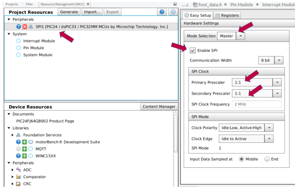
今回は初設定をMCCを使って行っています。SPIのクロックですが、PrimaryとSecondaryのPrescalerを共に1:1として最速としました。これで2MHzとなります。
次はIOポートの設定です。矢印の部分が変更箇所です。
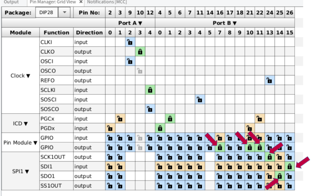
このLCDにはMISOポートが無いので回路にその記述は有りませんが、MISOポートをRB15に設定しています。RB7のLEDはデバック用に付ました。その他の項目は変更無しでGenerateしています。
プログラムの説明
今回書いたプログラムは、AQM1248A_PIC.c(本体)とAQM1248A_PIC.h(ヘッダーファイル)の2です。それと文字表示用のフォント、font_data.hを使用しています。それ以外はMCCが作成したコードです。メインプログラム。”main.c”では 点、直線、文字表示等 簡単なデモを行っています。
AQM1248A_PIC.cは、AQM1248A グラフィックLCD (for Arduino)に有るArduino用のプログラムをMCCで作成した関数(ほとんど、”SPI1_Exchange8bit()”)を使って書き直したのもです。各関数の説明はリンク先を参照して下さい。
AQM1248A_PIC.c
/*
 * File:   AQM1248A_PIC.c
 *
 * Created on December 7, 2021, 10:35 PM
 */

#include "xc.h"
#include "AQM1248A_PIC.h"
#include "font_data.h"
#include "mcc_generated_files/spi1.h"

uint8_t v_buf[128][6];

void Init_LCD()
{
    LCD_CS =  LOW;
    LCD_RS =  LOW;

    SPI1_Exchange8bit(0xAE);
    SPI1_Exchange8bit(0xA0);
    SPI1_Exchange8bit(0xC8);
    SPI1_Exchange8bit(0xA3);

    SPI1_Exchange8bit(0x2C);
    __delay_ms(50);
    SPI1_Exchange8bit(0x2E);
    __delay_ms(50);

    SPI1_Exchange8bit(0x2F);

    SPI1_Exchange8bit(0x23);
    SPI1_Exchange8bit(0x81);
    SPI1_Exchange8bit(0x1C);

    SPI1_Exchange8bit(0xA4);
    SPI1_Exchange8bit(0x40);
    SPI1_Exchange8bit(0xA6);
    SPI1_Exchange8bit(0xAF);

   LCD_CS = HIGH;
}

void LCD_CLS(uint8_t data)
{
    uint8_t a,b;

    LCD_CS = LOW;
    for(b = 0; b < 6; b ++)
    {
        LCD_RS = LOW;
        SPI1_Exchange8bit(0xB0 + b);
        SPI1_Exchange8bit(0x10);
        SPI1_Exchange8bit(0x00);

        LCD_RS = HIGH;
        for(a = 0; a < 128; a ++)
        {
            SPI1_Exchange8bit(data);
            v_buf[a][b] = data;
        }
    }
    LCD_CS = HIGH;
}

//----------------------------------------------------
//  点の描画
//  int x_data  X positon   0 -> 128
//  int x_data  Y positon   0 -> 48
//  int cl      color 0: white  1:black
//----------------------------------------------------
void LCD_PSET(int x_data, int y_data, int cl)
{
    uint8_t a,b,c;

//  y_data
    a = y_data >> 3; b = y_data & 0x07;
    c = 0x1;
    while(b) { c <<= 1; b --; }

    if(cl) v_buf[x_data][a] |= c;
    else { c = ~c; v_buf[x_data][a] &= c; }

    LCD_CS = LOW;
    LCD_RS = LOW;
    SPI1_Exchange8bit(0xB0 + a);
    c = x_data >> 4; c |= 0x10;
    SPI1_Exchange8bit(c);
    c = x_data & 0xf;
    SPI1_Exchange8bit(c);

    LCD_RS = HIGH;
    SPI1_Exchange8bit(v_buf[x_data][a]);

    LCD_CS = HIGH;
}

//----------------------------------------------------
//  Fontの描画
//  int x_data  X positon   0 -> 128
//  int y_data  Y positon   0 -> 48
//  char c_data Data
//  int cl      color 0: white  1:black
//----------------------------------------------------
void LCD_Print_C(int x_data, int y_data, char c_data, int cl)
{
    int a,b,c,d;
    unsigned char s,data_c;

    data_c = c_data;
    if(data_c > 0xbf) data_c -= 0x40;
    a = data_c - 0x20;
    for(b = 0; b < 5; b ++)
    {
        s = 0x1;
        for(c = 0; c < 8; c ++)
        {
            d = 0;
            if(Font[a][b] & s) d=1;
            if(cl == 0) d = !d;
            LCD_PSET(x_data,y_data + c,d);
            s <<= 1;
        }
        x_data ++;
    }
    for(c = 0; c < 8; c ++)
    {
        d = 0;
        if(cl == 0) d = 1;
        LCD_PSET(x_data,y_data + c,d);
    }
}

//----------------------------------------------------
//  Strの描画
//  int x_data  X positon   0 -> 128
//  int y_data  Y positon   0 -> 48
//  char *c_data Data
//  int cl      color 0: white  1:black
//----------------------------------------------------
void LCD_Print_Str(int x_data, int y_data, char * c_data, int cl)
{
    int a;

    a = strlen((char *)c_data);
    while(a)
    {
        if(*c_data == 0xff)
            { c_data ++; a --; }

        LCD_Print_C(x_data,y_data,*c_data,cl);
        a --; x_data += 6; c_data ++;
    }
}

//----------------------------------------------------
//   直線描画関数
//
//  int x0      start x
//  int y0      start y
//  int x1      end x
//  int y1      end y
//  int cl      color 0: white  1:black
//----------------------------------------------------
#define abs(a)  (((a)>0) ? (a) : -(a))
void LCD_LINE(int x0, int y0, int x1, int y1, int cl)
{
    int steep, t;
    int deltax, deltay, error;
    int x, y;
    int ystep;

    /// 差分の大きいほうを求める
    steep = (abs(y1 - y0) > abs(x1 - x0));
    /// x、yの入れ替え
    if(steep)
    {
        t = x0; x0 = y0; y0 = t;
        t = x1; x1 = y1; y1 = t;
    }
    if(x0 > x1)
    {
        t = x0; x0 = x1; x1 = t;
        t = y0; y0 = y1; y1 = t;
    }
    deltax = x1 - x0;                       //  傾き計算
    deltay = abs(y1 - y0);
    error = 0;
    y = y0;
    /// 傾きでステップの正負を切り替え
    if(y0 < y1) ystep = 1; else ystep = -1;
    /// 直線を点で描画
    for(x = x0; x < x1 + 1; x++)
    {
        if(steep) LCD_PSET(y,x,cl); else LCD_PSET(x,y,cl);
        error += deltay;
        if((error << 1) >= deltax)
        {
            y += ystep;
            error -= deltax;
        }
    }
}
添付したコードを実行するとAQM1248A グラフィックLCD (for Arduino)と同じデモプログラムを実行します。システムクロックは変更していないので4MHzですが、とても速く描写します。試しにシステムクロックを挙げたら描写が見えない位速くなりました。今回使用したコード一式を以下に保存します。